You are here: Home > Firearms > British Military Longarms > Snider-Enfield
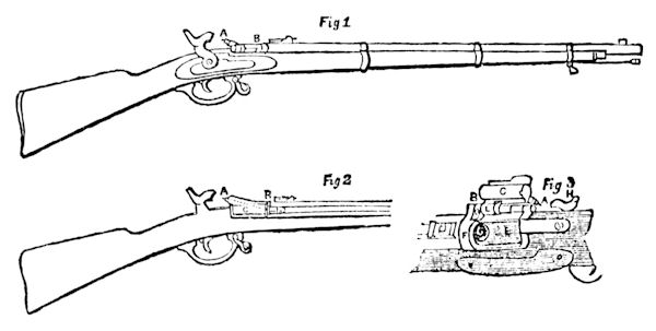
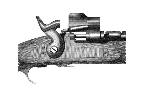
The construction of the Snider-Enfield.

In fig. 1, A is the pin in the centre of the nipple which traverses the breech cylinder; B is the hinge upon which the breech opens – the part of the hinge farthest from the hammer contains a spring. In fig. 2 the dotted line A represents the action of the pin passing through the breech to the cartridge in the barrel, C being the cylinder that fits into the breech. In fig. 3, A is the nipple and B the end of the hinge before referred to. A strong band, F, is placed over the orifice of the barrel, and within the cylinder, C, is the pin, as shown in fig. 1. D is for the finger to pull the cylinder out of the breech, in order to insert the cartridge; E is the breech; G, the orifice of the barrel; H, the hammer. L is the portion of the hinge containing the spring that pulls back the catch, O, which fits into the band. F is the rim of the cartridge resting against the catch; when pulled back it brings the cartridge case with it, and allows the case to be dropped out of the breech by the simple action of turning over the rifle.
Source: Pall Mall Gazette, 27 July 1866
