Projectiles and Rifling > Rifling Machines
The mechanical configuration of these grooves or riflings upon the gun previously bored to the old cylindrical or “smooth bore” form, has called forth several RIFLING MACHINES, some of which are of extreme beauty of combination.
The old rifling tool of gunmakers for small arms consisted mainly of a square rod, twisted to the same extent as the grooves were intended to have in the barrel. This carried a suitably formed cutter at one end, and slided through a square hole in the centre of a plate with a divided circumference. The divisions of the latter determined the number of grooves round the whole interior of the barrel, and the spaces between, and the form of the grooves, were fixed by it, and that of the cutter, the twist, as has been said, being that of the bar. The same arrangement has been applied to cannon; but the resistances to be overcome are here so much greater at the cutting point, the uniformity of the material not always the same, and the necessity for exact parallelism in all the grooves so imperative, that better machinery was early called for.
The rifling machine invented by Francois Jules Manceaux, a gunmaker of Paris, and patented in England in 1852 (No. 13,934), contains the germs of much that has since been achieved. Two of the most remarkable of these rifling machines are Mr. Lancaster’s, and that designed and perfected by Mr. John Anderson, C.E., Superintendent of the Royal Gun Factories, of which many are at work in the Arsenal, Woolwich. In Figs. 625, 626, Mr. Lancaster’s machine, patented in 1850 (No. 13,161), is generally shown. Fig. 625 represents the machine in sectional elevation and Fig. 626 a plan; Figs. 627 and 628 the longitudinal and transverse sections of the rifling bar and cutter head; and Fig. 629 the detail of the cutter head. Most persons now are aware that the Lancaster or oval-bored gun has an elliptic transverse section, and that, supposing the observer standing facing the muzzle, the major axis of the ellipse being vertical at that point, then at successive equidistant points taken back along the chase to the breech; the focus of this major axis is found, in a plane, vertical at the muzzle, and twisted spirally as it recedes towards the breech, either uniformly or according to any other determined law, and either to the right or the left hand of the observer; the twist being always about the axis of the original cylindrical bore – i.e., about the point bisecting the line joining the foci of the ellipse. The difference between the minor and major axes is extremely small – say, as 56:62, or even nearer equality. Thus, in fact, the Lancaster gun is a two-grooved rifle, in which the width of either groove is equal the minor diameter of the chase, and in which the “landes” have become evanescent. It is the simplest of all possible forms of rifling, and makes the nearest approach to leaving the old cylindrical bore untouched.
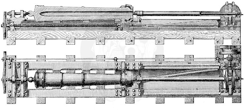
Fig. 625 (top) and Fig. 626 (bottom)
Lancaster’s Gun-rifling Machine – Sectional Elevation and Plan
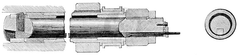
Fig. 627: Longitudinal Section of Rifling Bar
Fig. 628: Transverse Section of Rifling Bar
Having premised thus much, we can explain generally the action of the machine. The gun already bored cylindrical is fixed between bearings, placed upon cast-iron saddles that are free to move in the line of the V-beds of the machine. Between those beds is placed a guide-bar, as seen in Fig. 626, which is, in fact, the development upon a horizontal plane of the spiral to be traced upon the interior of the cylindrical chase of the bored-out gun; and the gun is so connected in its bearings with this guide-bar that, when caused to move endwise the length of its chase, it also rotates to the extent and in accordance with the line of the guide-bar. Thus all rifling may be reduced to spiral planing, applied to the interior surface of a gun.
Now, in this case, the rifling bar which enters the chase of the gun, and carries the planing cutter at its extremity, must be so arranged that the groove or cut produced by this cutter shall equal the full depth of the semi-difference between the major and minor axes at two opposite points, and at two others orthogonal to these, shall become evanescent – in other words, that the point of this cutter shall describe an ellipse in a plane transverse to the axis of the gun or of the rifling bar. This is effected by an extremely simple and beautiful mechanical arrangement. The rifling bar consists of two cylinders, one within the other; and the internal one is, as seen in section in Fig. 628, eccentric to the outer. The axis of the outer bar coincides with that of the gun to be rifled, and it is the slow rotation of this that determines the breadth of each new cut made by the spiral plan or cutter; as the gun, after having been advanced over the bar, until the extremity of the latter has reached the breech, is again withdrawn from over it, in which latter movement the cut alone is made. The rotation of the inner and eccentric bar within the outer determines the elliptical projection of the cutting-tool, which also at the end of each cut, is withdrawn (towards the axis of the gun), and at the commencement is again projected within these limits, by means of a wedge acting at its back end, and to which movement is given by a rod passing through the whole length of the bar to its external end. Those accustomed to mechanical arrangements will, from this too brief description, understand the simplicity and elegance of this tool. It may be right to mention that Lancaster does not confine himself to a mere elliptic section. He specifies a section of chase composed of two curves, joined by right lines which are common tangents to both; and this, we apprehend, would be found the best modification of his method.
The general excellence, both in regard to design and workmanship, of Mr. Anderson’s rifling machine, by which the Armstrongs, the shunt guns, and all others made by Government are now produced, and of which some dozens may be seen at work at Woolwich, claims for it more than a passing notice. The machine itself, as made by Messrs. Smith, Beacock, & Tannett, Victoria Foundry, Leeds, is exhibited in Class VII., No. 1715, in the Western Annexé; and, however inadequate may be a reward so lavished to a machine so perfect, received a medal with other tools by these makers, Mr. Anderson himself being precluded as a juror.
This machine is self-acting in all its movements. Unlike Lancaster’s machine, the gun here does not move in the line of its own axis, but the rifling bar does. The gun, fixed in hollow bearings, rotates on its own axis per saltum, as the cut changes from one groove to the next, as guided and restricted by the divided ratchet-wheel at its muzzle.
The rifling bar carries several cutters acting at once, and all cutting together, which is the grand guarantee for parallelism in the groves, and it is carried forward into the cut, and cuts upon being again drawn out, by means of a screw with alternate forward and backward movements.
The diagonal bar is the guide bar or development of the spiral, as already explained; if the latter be of uniform twist, as in a common screw, this bar will be straight; if, on the other hand, it be of increasing spiral, it will be as in Lancaster’s, a curve. The guide bar is variable as to the angle it makes with the end-on motion of the rifling bar, and this angle determines the amount of twist given to the groove in the length of the gun. The bearing block that carries the outer end of the rifling bar and forces it forward, as itself urged by the long screw, also forces a movable piece against the guide bar. This piece is in connection with the horizontal toothed rack, transverse to the length of the whole tool, and this communicates rotation to the rifling bar, and to the cutters in its head, so as to reproduce in the interior of the gun the envelope of the twist or spiral of which the guide bar is the development.
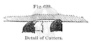
But this is not all; when the cut has been completed for one stroke, and the rifling head is to be again introduced into the gun to commence a second, the cutters must be so withdrawn, that, as the claws of the tiger are withdrawn within the integuments of the toes, out of danger of being blunted when not in use, these shall not be blunted by rubbing down along the chase. This is done by the motion of a roller and certain movable pieces. The cutters are all held up to or withdrawn from their work by certain inclined planes, or wedge pieces (the surface of a cone, in fact) in the interior of the cutter head; all of which are acted upon by a rod that passes through the hollow centre of the rifling bar, and the movement of which controls them all, while it is itself controlled by the master guides and roller, which follows the end-on movement of the rifling bar; bringing the cutters all, and to equal depth, into cutting action at the commencement of the outgoing stroke, and vice versa, and determining the final depth of every groove – the bar, of course, pulling out of the chase its own shavings along with itself.
There are many details of this machine that we wish space were afforded us to describe; and we have also to regret that the same cause prevents our giving here the admirable bullet-compressing machine, for which Woolwich Arsenal is also indebted to Mr. Anderson.